 |
 |
Manned Ornithopters Full History History Archive
Getting Started How to Design & Build Competition Info Design Tools
Design Manual Newsletter Free Plans
Teachers Guide Web Site Links
About the Society Contact Info |
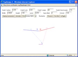
FlapDesign How to use Use FlapDesign to find the correct dimensions when you design an ornithopter wing-flapping mechanism. Run FlapDesign Getting Started A new feature has been added since these instructions were written. The "transverse" feature does not appear in the illustrations at this time, but is explained below. 1. Once the program has time to load, you will see the FlapDesign interface. This consists of several boxes, where you can type in the dimensions of your flapping mechanism, and several control buttons. First, we'll look at the three buttons on the lower right. 2. These three buttons are built-in examples. When you click one of the buttons, the dimensions for the appropriate mechanism will be displayed in the boxes, and you will see a front view of the mechanism in the area below the interface. You can use the examples to familiarize yourself with the program before typing your own dimensions. 3.
The examples represent three general types of ornithopter mechanisms.
However, the dimensions
were taken from actual designs. Below,
I've described the three ornithopters and how their mechanisms differ.
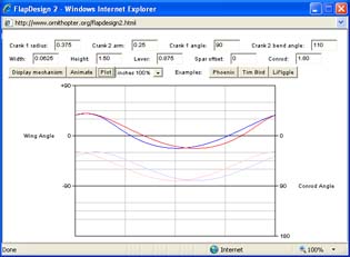
4. If you click the "Animate" button, the crank will move through one full rotation. You can also reposition the crank by dragging your mouse. The color-coded numbers on the diagram reveal the angle of each wing and (in lighter colors) the angle between the connecting rod and the wing lever. 5. Click the "Plot" button to display a graph of wing angle as the crank rotates. The red and blue curves correspond to the color-coded wings in the front view diagram. The lower graph, in lighter colors, shows the connecting rod angles. 6. Click the "Transverse" check box (not shown in illustrations) to make the crankshaft run side to side in the ornithopter. You can type a number for TW (transverse width) to indicate the width between the left and right crank arms. Your Own Mechanism 1. You can enter your own numbers in the fields at the top of the page. After each entry, click "Display mechanism" to show the changes.
2. Some dimensions may require a negative sign. Load the appropriate sample mechanism to see how to set up the particular type of mechanism you want to study. 3. If the connecting rods are too short or too long, the mechanism may not fit together properly. The program cannot correctly render such mechanisms. To avoid mechanical problems in real mechanisms, try to keep the connecting rod angles between 30 and 150 degrees. 4. Change the scale setting if you want to work in centimeters or if your mechanism won't fit in the display window. When set to "inches 100%", the actual scale is 72 pixels per inch, which may not be actual size on your particular monitor. Using a graphics editing program, you can print screen snapshots at 72 pixels per inch for an actual size representation of your mechanism. 5. The "Plot" button is useful if you want to look at timing differences between the two wings. If the wing plots are close together, the flapping motion will be symmetrical. The graph of connecting rod angle shows how the mechanical advantage varies throughout the stroke. 6. Biplane and
tandem ornithopters are not supported. You'll have to model the
upper and lower wings separately. Use a graphics editing program
to superimpose the wing angle plots.
|
|||||||||||||||||||